
- Home
- Deceptions
- Solar
- Thermal Audit
- Ventilation
- Sensors
- Governance
- Environment
- Reference
- Contact
- News
Consumer Warning
How to replace a failed Venmar Motor
(also sold as Venmar, Flair ,vanEE, Conformax, NuTone, Carrier, Bryant, Payne, Heil, York, Sears OPTIMUM,Guardian by Broan and more ...)
These motors fail regularly and sometimes overheat, and there has been one recall already. Replacement assemblies are quite expensive (close to $300 installed) so you may want to purchase a motor and replace it yourself to save some money. This guide will help you decide if you are up for the task. There is also a experiment on making it intelligent enough to detect people and vent accordingly (on-demand ventilation) based on the carbon dioxide being exhaled over here.
Tools required:
- 4 mm hex or allen key (metric)
- Phillips (star) screw driver
- wire cutters or pliers that can cut wire
- wire nuts, crimp connectors or something to connect electrical wires.
- a replacement motor such as a Roto M brand, model R462.
- about 2 hours of time if you have never done something like this before
Procedure:
Unplug the heat exchanger from the wall socket! You do not want to get an electric shock.
Open the heavy door by releasing the two plastic latches at the bottom front of the unit. Prop it open so that it isn't in the way so that you don't have to keep it open with your head or some other awkward stunt.
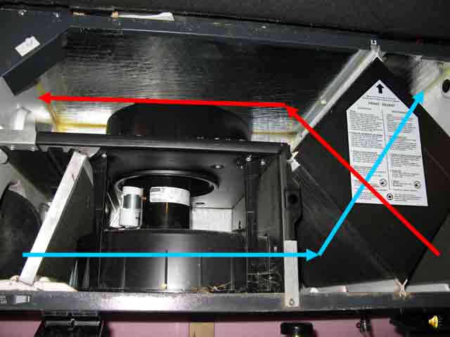
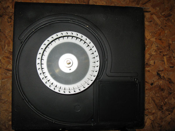
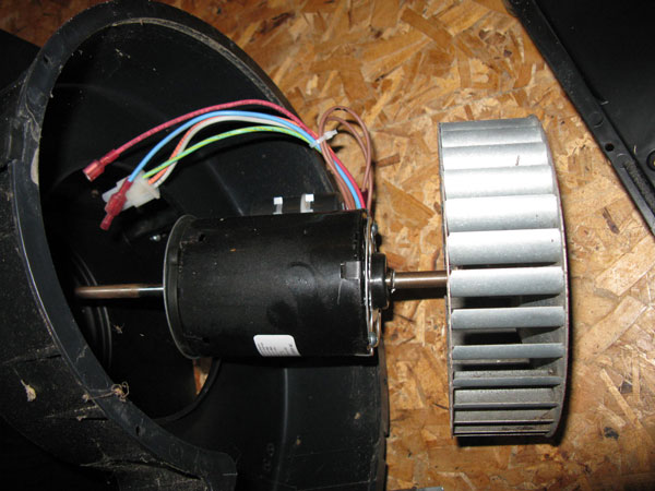
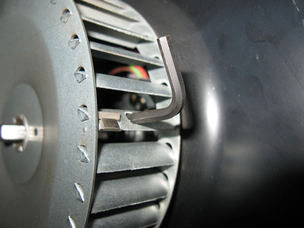
There are only two screws holding the fan assembly onto the edges of the heat exchanger housing. Remove them. You can see one of them in the photo below, and the bottom of the photo, just to the right of center.
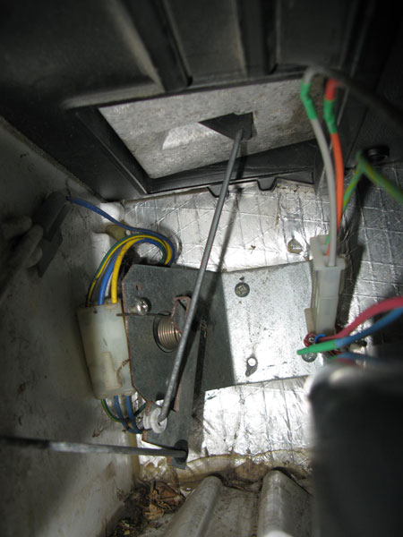
Disconnect the wires going to the motor. One of these is a white plastic connector with three wires that has a small latch that must be squeezed. If you do it right, very little force is required to separate the two halves. The red spade connector can just be pulled apart. The white, three wire connector is polarized and there is only one way it can go together, so you don't need to label anything. The red spade connector is the low speed fan wire. Depending on which wire from the motor you connected it to, low will be either motor-low or motor-medium.
Pull out the two air filters.
Disconnect the rod to the bypass damper door. It is about 6 inches long. The lower end of the rod is into a rubber grommet so it is much easier to disconnect this end rather than the connection to the door.
Pull out the heat exchanger core. This is the big, black, diamond shaped block. It will slide out freely, but may be a little stiff so you may have to wiggle it a little.
With the wires disconnected, the rod to the bypass disconnected, the filters and core removed - the fan assembly will come out freely. Take it out and lay it on the floor.
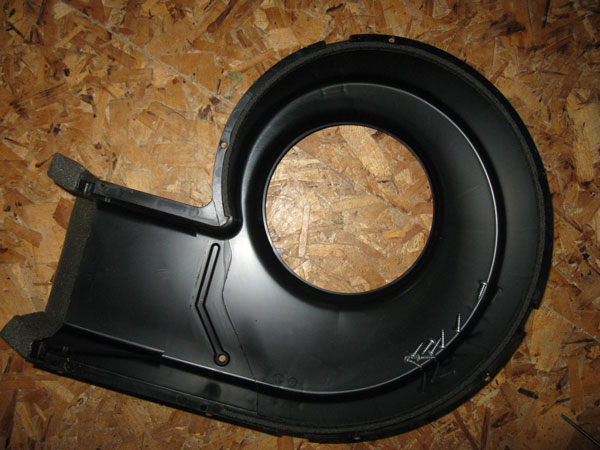
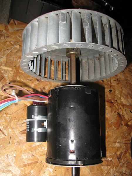
Next, remove the small screws holding the duct shrouding to the larger assembly, and you should see something like this picture below.
The piece that was removed is shown in the next slide:
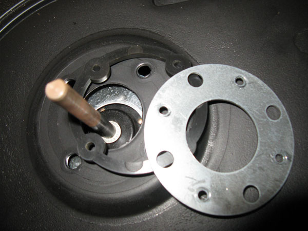
Mark the shaft with a permanent marker so that you can put the fan blade back where you found it, although you will likely find centering it later not that difficult. Remove the fan blade (squirrel cage) using a 4mm allen key. You only need to loosen the set screw a quarter turn. When you reassemble it, if the squirrel cage scrapes against the plastic fan housing, you will need to center it manually before tightening the set screw.
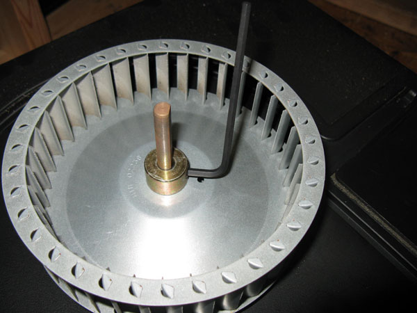
The fan will then slide off the shaft and you will see a shaft and the motor vibration isolation flange.
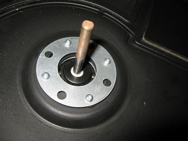
The four screws pass through two metal rings and two rubber gaskets and thread into the motor body. Remove the four screws.Note the orientation of the rubber gasket for reassembly later. There is no harm in using a sharpie permanent marker to label the tops of everything and their orientation to help you remember how to put it all back together.
The motor will now come out from the other side like this. There was a large circular, flat, black plastic cover over the end of the fan assembly which was removed earlier. You should be able to remove it with your fingers by prying it off at the edges.
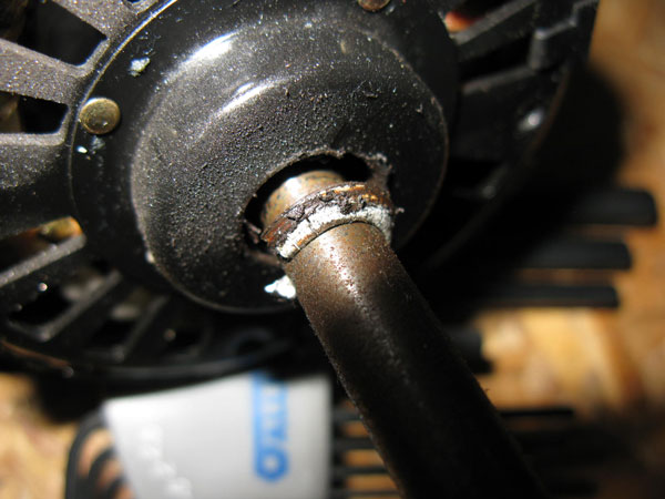
Next, remove the isolation ring on the motor shaft. Note the the rubber gasket is between the ring and the motor.
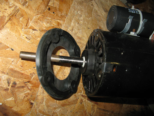
Now we can see what the problem was. This motor probably doesn't like being operated vertically and the bearing has failed. There is a lot of play on the shaft and the seal is clearly broken and full of small cracks. Lets hope FASCO has improved their design.
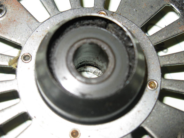
You don't need to do the following, but I took one apart to see what went wrong inside. Here is a what the sleeve bearing looks like.
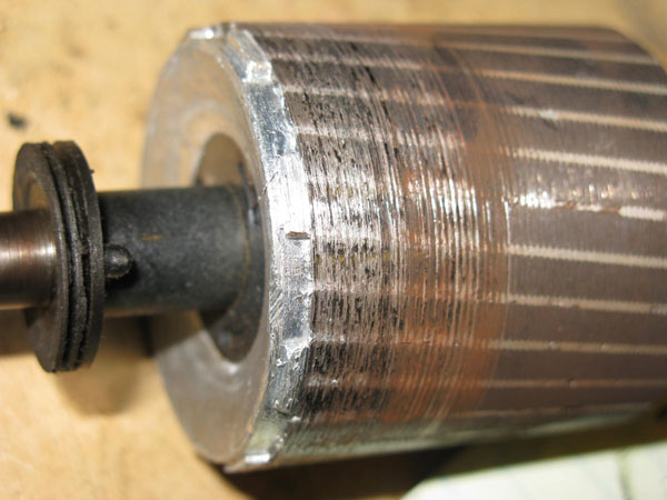
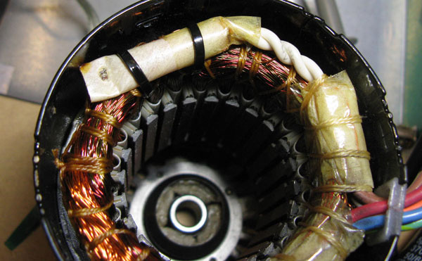
When the bearings wear excessively after a year or two of operation, the rotor of the motor starts rubbing against the stator and you see this:
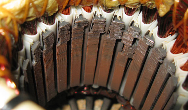
Unfortunately, the rotor, which on an induction motor is a sturdy hunk of iron and aluminum bars, destroys anything it contacts. The image below shows the steel laminations have been destroyed. The vertical slots were originally in straight lines, not broken up as in the image below. Since their edges are sharp, they can easily cut through the stator winding insulation and short them together, creating an electric heating circuit instead of a motor. This has the potential to get much hotter than the motor would if you were to simply stall it by having the bearings seize. This motor is bolted onto a rubber seal which can burn and the fan shroud is made of plastic -- so this is a recipe for disaster.
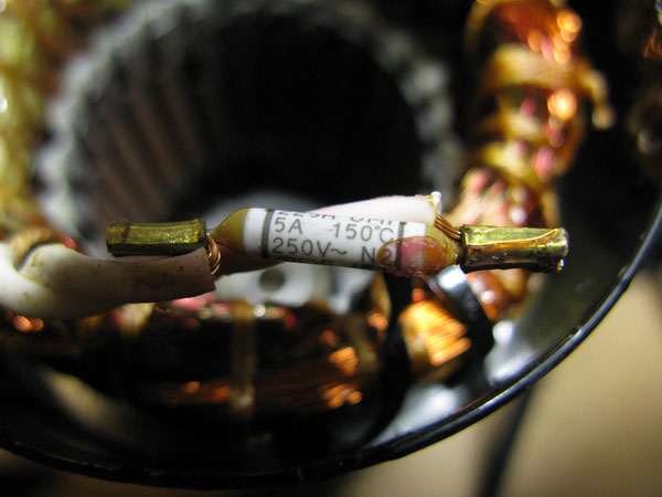
Now looking a little close at the problem, notice the location of the thermal protection fuse. If the windings that overheat and short (and in this case, the destroyed section of the core is directly opposite of the fuse) are on the other side, then it is going to take a while to blow.
The FASCO fuse is covered in the photo above with a plastic sleeve, but is exposed here. It cuts out at 5A or 150C (300F).
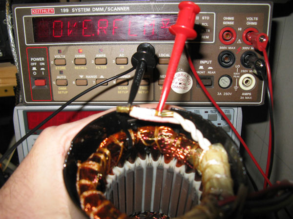
Now we test the fuse and see that is an open circuit (blown).
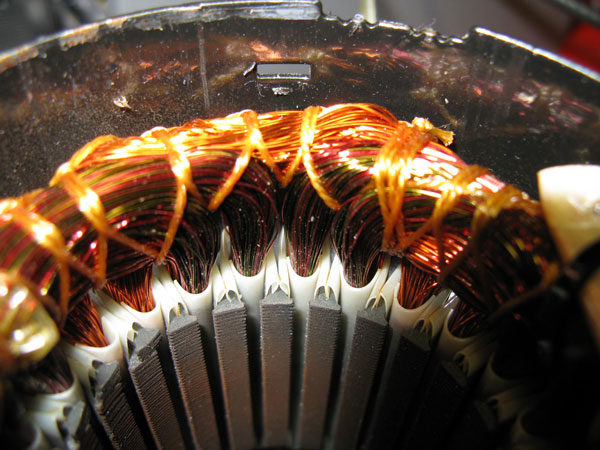
If you look close at the picture above and the picture below, you can see that there are dark areas on the coils of copper wire where the clear insulation coating on the copper wire has charred.
So there you have it. One realistic sequence of events leading to a fire would be this:
- The sleeve bearings wear out (this has happened to me multiple times)
- The rotor smashes the core and cuts up or shorts out various windings (see photo above)
- The windings get very hot (as proven by the charred insulation above)
- The windings that get the hottest just happen to be far away from the thermal fuse or you have an older motor that doesn't even have a thermal fuse
- The ultra hot motor is mounted directly against a rubber ring (you can see it in the motor replacement instructions) and bolted to a plastic fan housing which can melt and burn.
- There is additional fuel available since the heat exchanger core is also plastic
- Presto -- box with fire coming out of it to burn your house down.
Don't worry too much, this isn't going to happen very often - just like babies don't killed in drop side cribs very often.
Obvious ways to reduce this possibility are:
- Use a motor with quality ball bearings so that they don't fail very often.
- Choose a motor where the rotor cannot destroy the core and shatter it like the one above
- Install a thermal cutoff that measures the temperature of the end of the motor that is bolted to the fan assembly.
- Do not bolt the motor to anything that can burn.
What Venmar needs to do:
- Design a upgraded fan assembly with a quality motor, and where the the worst case (motor draws 15A, the max before your wall socket blows and gets smoking hot) is attached to nonflammable parts and far enough away (via a heat sink or distance) that no plastic parts can possibly burn.
- Provide a free swap in replacement to all their customers or offer them a newer model for free.
- Offer 100% refund of list price (most people had it come with their house, so they don't have invoices)
What Venmar will likely do: Nothing. Unless they get sued or forced into another recall by government action. Like most corporations, they are sociopath's that are do whatever makes their shareholders the most money, regardless of the consequences to others. There are a few companies like Costco or Honda or founder owned businesses that still care about society but these are becoming rare exceptions.
-- end of what you don't need to do.
Remove the old capacitor (the cylindrical or oval can) on the side of the motor and then remove the capacitor bracket. Transfer this bracket to the new motor.
Reassembly of the unit is the reverse of what you just did, however, there are a few things to watch out for. One of the fan assemblies has a convenient hole in one of the blades so that you can get at the set screw, which is convenient.
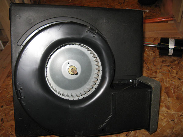
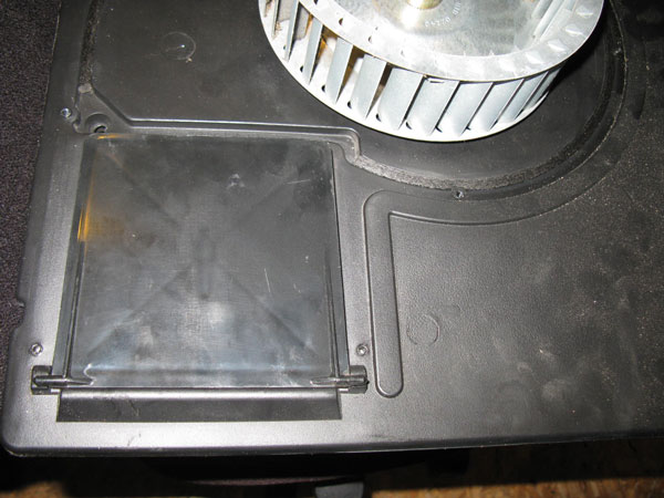
When you replace the fan shroud, ensure the trap door is positioned as shown below, with the hinges in the recesses. If you leave the door out, you won't be able to get it into position later without taking everything apart again.
Once the shroud is in place, lift the fan blades up and then let them fall down the shaft. You will find that there is about a quarter inch of play. You don't want the blades to be rubbing the plastic housing so position it half way in between, and then tighten the set screw with the allen key. When you are finished, the fan should rotate freely without any rubbing or scraping sounds.
You may need to change the electrical connectors on the motor. Keep in mind the following:
- The color codes on the old and motors are the same, although the shades of orange and red may be different. There is a color code diagram printed on the motor label.
- There are more wires on the motor than you will be using. The Venmar supports two speeds. You have a choice of any two of high, medium or low speed. I chose high and low. The unused wire needs to be protected with some kind of connector to prevent it from giving you a shock.
- The simplest thing to do is just to match up the wires by color and connect them rather than experimenting with new fan speeds.
- The new motor wiring harness is not very long. You can cut off the old connectors with a few inches of wire attached and graft these on to the new motor. This will give you a longer wiring harness and avoid having to special order replacement connectors. You can solder the wires together and use heat shrink tubing, or twist them together and use wire nuts to secure them or use insulated crimp connectors. Whatever you do, do NOT just twist them together -- they need some kind of mechanical connection to ensure they stay tightly connected.
- The capacitor has two brown wires connected to it. These wires likely already have connectors installed. Connect them to alternate sides of the capacitor. You do not want to short them out. In the capacitor shown below, you don't have any choice. However, in the capacitor that follows (two pictures down), there are six places to connect wires, so be careful.
- Use some tie wraps when everything is back together to make sure the wires aren't rubbing on anything and well clear of the fan blades.
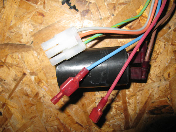
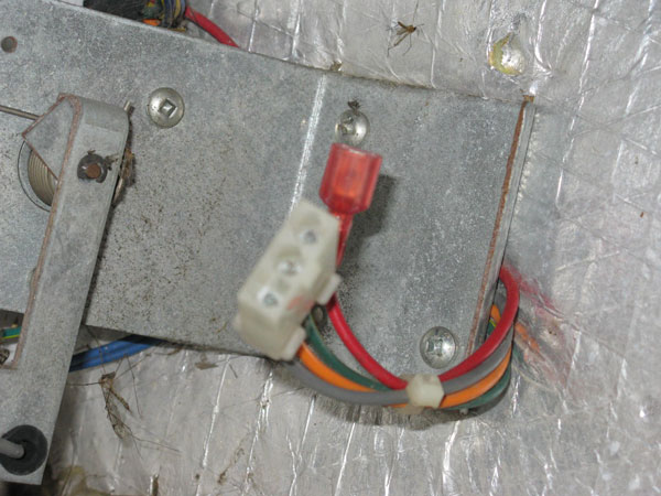
The photo above shows the old capacitor (black can) connected to the two brown wires. The blue wire has an empty female connector on it to prevent it from touching anything. The red wire (low speed wire) was connected to the heat exchanger wiring harness. If the blue wire had been connected to the wiring harness instead of the red, the two speeds available would have been medium and high.
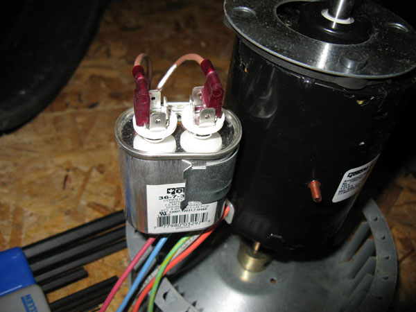
In the picture above, the new capacitor is silver and larger, but still fits the clip. You will have to reposition the capacitor when you install the motor so that it doesn't get in the way.
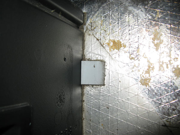
When you slide the fan unit back in, put it in at a slight angle and make sure the back edge is behind the protruding piece of metal in the photo below. then straighten the fan assembly. This metal bracket ensures that the unit is forced snugly into the corner of the box.
If you look closely, in the first photo, the motor capacitor is white. Photo 16 shows a black capacitor. Photo 17 shows a silver one. So just how many motors have I replaced in this Venmar? Too many. Far too many. Venmar does a lousy job at engineering design and should be ashamed of themselves.
That's it. I hope it all went well for you and that your new motor lasts a lot longer than my last four motors did!