
- Home
- Deceptions
- Solar
- Thermal Audit
- Ventilation
- Sensors
- Governance
- Environment
- Reference
- Contact
- News
Pressure Testing for Air Infiltration
How to make a window mounted blower and perform a 50Pa depressurization test and avoid the expense of a blower door.Houses normally have hundreds of small leaks, such as gaps around windows, doors and baseboards, which are noticeable at times as drafts. Although this air infiltration increases the heating and cooling costs, it also maintains indoor air quality. There is a trend in modern buildings to seal the house with plastic vapor barriers to absolutely minimize air leaks and then use mechanical ventilation systems such as heat exchangers to provide air exchange.
In order to determine if a new house is well sealed (its tightness) or if an older house is getting too much or too little air exchange, pressurization tests are often performed. The most common setup is a blower door which consists of a fabric sheet to cover the door opening and a built in fan.
An alternative is to make a window mounted blower unit. Start by finding a high volume fan that you can fit in a window opening. The one pictured below came from a farm supply superstore and rated for continuous duty. Larger is better, but make sure it can fit into one of your windows. Alternately, you could use it in a door way as long as you can rig up a tarpaulin to cover the rest of the door opening.
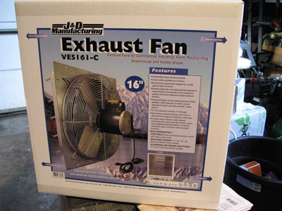
This is what it looked like when taken out of the box.
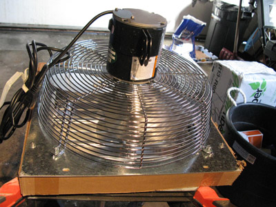
The next step is to mount a frame around it. We used a piece of 2"x6" spruce, cut it and made a frame like this:
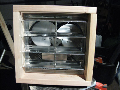
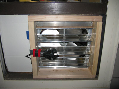
This allows it to fit into a window cavity like this, without scratching the window sill.
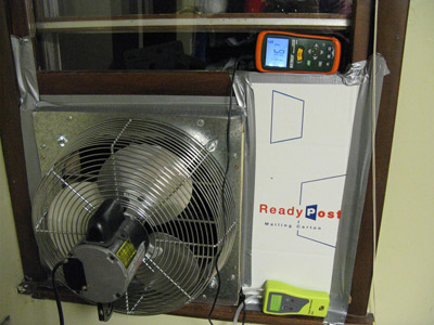
Here we opened the window, positioned the fan, closed the top window down to meet the fan frame and plugged the hole to the right with a piece of cardboard and some duct tape.
The red instrument above is an air velocity meter for calculating the air flow rate. The yellow instrument is a differential manometer that can read pressure differences as small as 1 pascal. The pressure difference we will be measuring is very small. Standard atmospheric pressure at sea level is 101325 Pascals so a difference of 50 pascals will not pop your ears, and is about a tenth of the 480 pascals that normally builds up in your ears over night when you don't swallow or chew much. The manometer has two hoses. One is dangling down towards the floor and the other is pushed through a hole in the cardboard and is dangling down the outside wall.
This is a view from outside the window. A small 4"metal bracket was screwed onto the frame and two Velcro straps were used to fasten the sensor to the air flow meter.
Next is to find a way to vary the fan speed since this is a single speed fan. This kind of fan can be controlled with a motor controller (not a lamp dimmer). Below is a picture of one that worked well but was probably overkill.
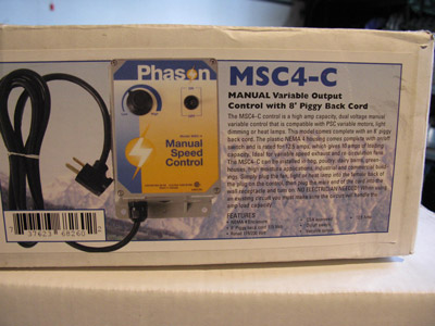
This particular unit does not have an output cord, so we had to open it up and add a piece of cord with a female plug for the fan to plug into. You can probably find a fan controller that is pre wired.
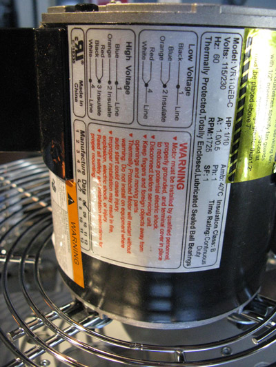
This particular fan was rated for 1725 cubic feet per minute. However, this rating is possible only when there is no pressure drop. As the house begins to depressurize, the fan output drops considerably as the pressure difference increases, decreasing to about half its rated output. Therefore, if you have a drafty home, you will probably need a fan that is rated about 3000 cfm. If you look at the label below, you will see this fan is rated at 1/10 horsepower. You probably want something more powerful if you want to be sure to achieve a 50Pa pressure drop.
Testing Procedure:
- Zero the manometer as per the meter's instructions. Start the fan on high speed. The pressure reading will begin to change after several seconds and slowly climb. Use the averaging feature of the air flow meter if available, and starting making a list of flow rate / pressure drop pairs.
- Lower the fan speed a small quantity, and wait for the manometer to drop a few pascals. Let the pressure reading stabilize (this might take 5 or 10 seconds) and then record another flow rate / pressure pair.
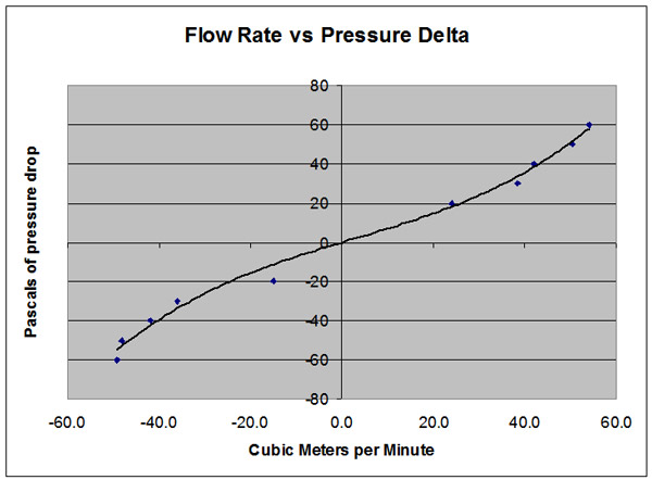
- Graph the data pairs with a spreadsheet. You will get something like the following:
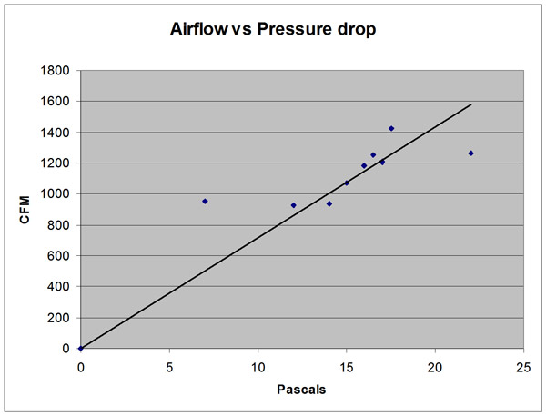
You will probably not get a nice tight fit to a line in most homes unless you can control variables like people opening and closing doors, bathroom and kitchen fan usage, opening doors and large gusts of wind. In this example, we tried opening a nearby basement door and saw the pressure differential drop immediately to zero. The vacuum created also extinguished the pilot light on the natural gas hot water heat probably by sucking air down the tank exhaust pipe.
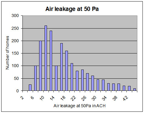
The graph below is what you expect based on the sample data in the ASHRAE handbooks:
Data Analysis
Rule of thumb #1: ( Air exchanges per hour at 50 Pascals ) / 20 = natural air exchange rate.
If you measured 3200 CFM at 50 pascals, and you have a two story house of 3000 square feet with 8 foot ceilings, then:
Home air volume = 3000sf x 8ft = 24000 cubic feet.
Air exchanges per hour at 50 Pa = (3200 cfm * 60 )/ 24000 cf = 8
Natural air exchange = 8/20 = 0.4 ACH (Air changes per hour)
One common idea is that a house needs 0.35 ACH to maintain indoor air quality. A value of 0.4 indicates that this house is slightly draftier than necessary, and that adding mechanical ventilation such as a heat exchanger would be a waste of money. It also indicates that significantly tightening the building envelop (sealing every crack you can find) might cause the house to become stuffy and cause the occupants to frequently open the windows to get fresh air.
Another interesting comparison is to see where this fits into other houses in your area. For example, we have 8 ACH above, which is just to the left of the peak of the graph below. Therefore, the value is typical, and slightly towards the tighter side of things. Of course knowing where you fit into the pack of scurvy dogs is not that useful. The existing stock of homes in North America is not a good role model.
Rule of thumb #2:
An ACH 50 (air exchanges per hour at 50 Pa) less than three needs mechanical ventilation. In this example, we have 8, so additional mechanical ventilation is not needed.
Air Leakage Area:
The air leakage area is the equivalent sized hole (a pretend hole) in the house that would give the same amount of air infiltration. The experimental formula for this (in square centimeters) is:
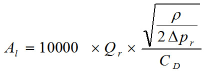
Qr is the estimated air flow rate with a pressure difference of 4 pascals in cubic meters per second
CD is the discharge coefficient (usually equal to 1)
Pr is the reference pressure drop (4 Pascals)
p is the air density (1.2 kg/m3)
Since this is getting ugly for a web page, I will add a on-line calculator for this soon.
If you estimated an airflow rate of 0.1 m3/s to be the airflow rate at 4Pa, then you will get a 387 cm2 hole equivalent to 8 inches or 22 centimeters in diameter.
This is good for conceptualizing the extent of the leakage.
Normalized Leakage:
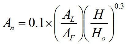
AL is the leakage area at 4Pa
AF is the floor area of the house in square meters
H is height of the house in meters
HO is the reference height of 2.5 meters
The purpose of this is to adjust the leakage area based on the size of a house so that houses can be compared. You would expect a large house to leak more air than a small house and taller houses to leak more than shorter houses because of the stack effect, so unless you "normalize" the measurements, you really can't use the unadjusted values for comparing non identical houses.
Other Models:
If you know the heating degree days in your area and average wind speeds there are better models that allow you to more accurately predict what the natural air exchange rates might be.
Stay tuned ... this will get built in calculator soon. I am sure the commercial blower doors come with built in software, but I haven't seen any open source software to do the calculations. This will change soon.
-- end --